

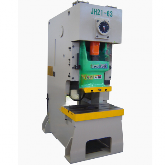
JH21 series Open front and fixed bed press with dry clutch and hydraulic overload protector
Main features:
1. Welded body with steel plate and high intensity.
2. Main motor is made by Siemens.
3. Adopts combined pneumatic friction clutch and brake.
4. Cluster gear adopts the flooding oil lubrication.
5. Six-face rectangle lengthen guide; JH21-315B/400B adoptseight-face lengthen guideway.
6. Equipped with hydraulic overload protecting device.
7. JH21-25/25B/45 adopts manual shut height adjustment,amongthese types JH21-25/45 adopts scale display and JH21-25B with digitaldisplay.JH21-63 and above type adopts electric shut height adjustment withdigital display.
8. JH21-45 can equip with die set height adjustment motor, thevalue will be displayed by digital.
9. JH21-25B, JH21-45 and above type equipped with balancecylinder.
10. Duplex valves imported.
11. Electric compelling grease lubrication system.
12. Balancing cylinder adopts manual lubrication system.
13. One set of blowing device.
14. Controlled by PLC with international brand.
15. Buttons, indicators, AC contactors, air circuit breakers andother controlling devices are imported from international brand.
16. Equipped with optional air cushion device, automatic feedshaft and photoelectric protector,which can used to work with various automaticequipments.
Description
| Description | Unit | JH21-25B | JH21-25 | JH21–45 | JH21-63 | JH21-80 | |
| Capacity | kN | 250 | 250 | 450 | 630 | 800 | |
| Nominal Stroke | mm | 3 | 3 | 4 | 4 | 5 | |
| Slide Stroke | mm | 60 | 80 | 100 | 120 | 140 | |
| SPM | Fixed | min-1 | 100 | 100 | 80 | 70 | 60 |
| Variable | 80-120 | 80-120 | 70-90 | 60-80 | 50-70 | ||
| Max. Die Height | mm | 200 | 250 | 270 | 300 | 320 | |
| Die Height Adjustment | mm | 50 | 50 | 60 | 80 | 80 | |
| Between Slide Center & Frame | mm | 160 | 210 | 230 | 300 | 300 | |
| Bolster (FB×LR) | mm | 300×680 | 400×700 | 440×810 | 580×900 | 580×1000 | |
| Bolster Opening (Up Hole Dia.×Dpth×Low Hole Dia.) | mm | 130×260 | φ170×20×φ150 | φ180×30×φ160 | φ200×40×φ180 | φ200×40×φ180 | |
| Bolster Thickness | mm | 70 | 80 | 110 | 110 | 120 | |
| Bolster Opening (Dia./FB×LR) | mm | 200×270 | 260×250 | 300×300 | 390×460 | 390×520 | |
| Slide Area (FB×LR) | mm | 270×330 | 300×360 | 340×410 | 400×480 | 420×560 | |
| Shank Hole (Dia.×Dpth) | mm | φ40×60 | φ40×60 | φ40×60 | φ50×80 | φ50×80 | |
| Between Columns | mm | 448 | 450 | 550 | 560 | 640 | |
| Main Motor Power | kW | 3 | 3 | 5.5 | 5.5 | 7.5 | |
| Outline Size (FB×LR×H) | mm | 1150×1050×2050 | 1300×1050×2050 | 1390×1200×2400 | 1580×1210×2520 | 1640×1280×2700 | |
| Net Weight | kg | 2200 | 2600 | 3450 | 5400 | 7000 | |
| Description | Unit | JH21-110 | JH21-125 | JH21-160B | JH21-200 | JH21-200B | |
| Capacity | kN | 1100 | 1250 | 1600 | 2000 | 2000 | |
| Nominal Stroke | mm | 6 | 6 | 6 | 6 | 6 | |
| Slide Stroke | mm | 160 | 160 | 160 | 180 | 200 | |
| SPM | Fixed | min-1 | 50 | 50 | 40 | 35 | 35 |
| Variable | 40-60 | 40-60 | 35-50 | 30-40 | 30-40 | ||
| Max. Die Height | mm | 350 | 350 | 350 | 390 | 450 | |
| Die Height Adjustment | mm | 80 | 80 | 110 | 110 | 110 | |
| Between Slide Center & Frame | mm | 350 | 350 | 380 | 390 | 390 | |
| Bolster (FB×LR) | mm | 680×1150 | 680×1150 | 740×1300 | 760×1400 | 760×1400 | |
| Bolster Opening (Up Hole Dia.×Dpth×Low Hole Dia.) | mm | φ260×50×φ220 | φ260×50×φ220 | φ300×50×φ260 | φ300×50×φ260 | φ300×50×φ260 | |
| Bolster Thickness | mm | 140 | 140 | 150 | 160 | 160 | |
| Bolster Opening (Dia./FB×LR) | mm | 420×540 | 420×540 | φ470 | φ470 | φ470 | |
| Slide Area (FB×LR) | mm | 500×650 | 540×680 | 580×770 | 600×800 | 600×800 | |
| Shank Hole (Dia.×Dpth) | mm | φ60×80 | φ60×80 | φ65×85 | φ65×90 | φ65×90 | |
| Between Columns | mm | 760 | 760 | 850 | 870 | 870 | |
| Main Motor Power | kW | 11 | 11 | 15 | 18.5 | 18.5 | |
| Outline Size (FB×LR×H) | mm | 1850×1450×3060 | 1850×1490×3060 | 2280×1550×3240 | 2500×1580×3320 | 2500×1580×3420 | |
| Net Weight | kg | 9340 | 9900 | 14500 | 17000 | 17350 | |
| Description | Unit | JH21-250 | JH21-250B | JH21-315 | JH21-315B | JH21-400 | JH21-400B | |
| Capacity | kN | 2500 | 2500 | 3150 | 3150 | 4000 | 4000 | |
| Nominal Stroke | mm | 8 | 8 | 8 | 8 | 10 | 10 | |
| Slide Stroke | mm | 200 | 250 | 200 | 250 | 200 | 250 | |
| SPM | Fixed | min-1 | 30 | 30 | 30 | 30 | 25 | 25 |
| Variable | 25-35 | 25-35 | 25-35 | 25-35 | 20-30 | 20-30 | ||
| Max. Die Height | mm | 430 | 500 | 430 | 550 | 430 | 550 | |
| Die Height Adjustment | mm | 120 | 120 | 120 | 120 | 120 | 120 | |
| Between Slide Center & Frame | mm | 420 | 420 | 420 | 460 | 420 | 490 | |
| Bolster (FB×LR) | mm | 800×1400 | 800×1400 | 800×1400 | 880×1600 | 760×1400 | 940×1800 | |
| Bolster Opening (Up Hole Dia.×Dpth×Low Hole Dia.) | mm | φ320×50×φ280 | φ320×50×φ280 | φ320×50×φ280 | φ320×50×φ280 | φ320×50×φ280 | φ320×50×φ280 | |
| Bolster Thickness | mm | 170 | 170 | 170 | 200 | 180 | 200 | |
| Bolster Opening (Dia./FB×LR) | mm | 370×570 | 370×570 | 440×580 | 440×580 | 440×580 | 440×580 | |
| Slide Area (FB×LR) | mm | 650×850 | 650×850 | 650×850 | 700×950 | 690×900 | 720×1000 | |
| Shank Hole (Dia.×Dpth) | mm | φ70×90 | φ70×90 | φ70×90 | φ70×90 | φ70×90 | φ70×90 | |
| Between Columns | mm | 960 | 960 | 920 | 920 | 960 | 960 | |
| Main Motor Power | kW | 22 | 22 | 30 | 30 | 37 | 37 | |
| Outline Size (FB×LR×H) | mm | 2730×1640×3550 | 2770×1700×4060 | 2770×1650×3550 | 2850×1700×4450 | 2830×1680×3890 | 3100×1900×4600 | |
| Net Weight | kg | 23500 | 24500 | 25000 | 28000 | 29500 | 34000 | |
Related products
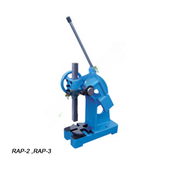
Batch sheel arbor RAP-2,RAP-3,MP-800
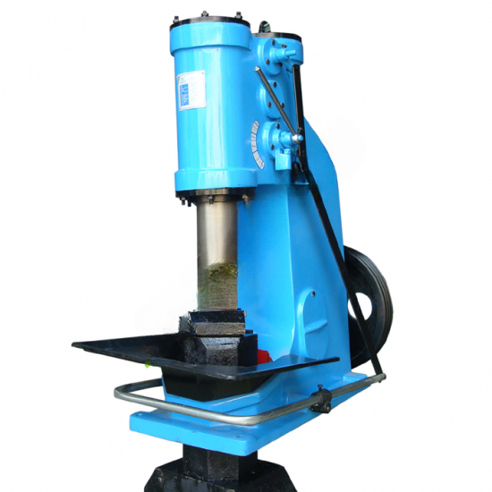
Air hammer C41
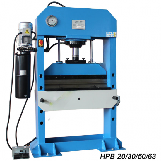
Hydrauli press HP series
Copyright ©2025 Prestige Industrial Services Ltd. All rights reserved.
